RANGKAIAN 7805 REGULATOR

7805 REGULATOR IC
7805 REGULATOR Schematic
If you'd like to build a little electrical power provide +5 V, the 7805
regulator is a superb selection, specifically for experiments with
digital circuits since the type of IC is commonly available [...]
Loop Control Automatic Reversing Circuit
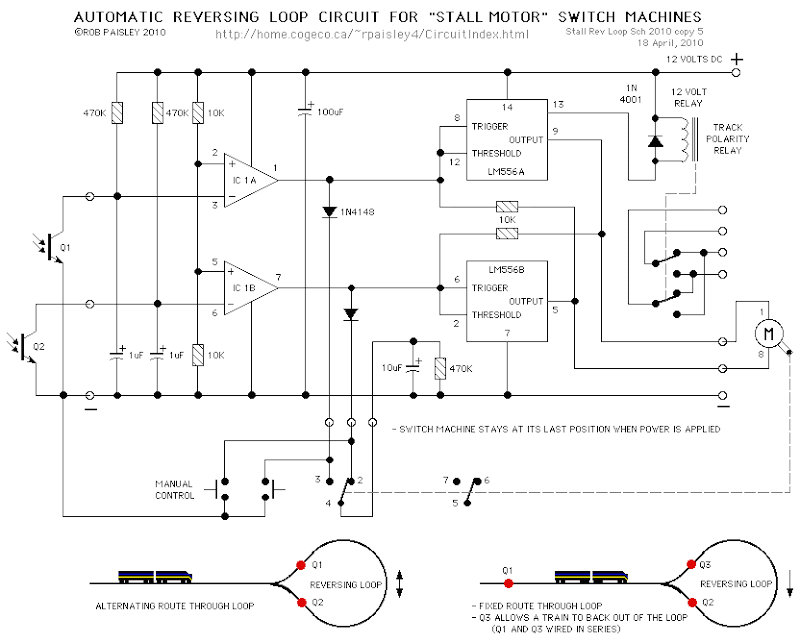
Loop Control Automatic Reversing CircuitAutomatic Reversing Loop Circuit - Notes* It is not the purpose of this page to provide a detailed explanation of the IC's used by this circuit. If you want more information on this subject please refer to the [...]
LM56 Thermostat Project Circuit Diagram

LM56 Thermostat Project Circuit Diagram values of R1, R2 and R3 for the required trip points VT1 and VT2 can be determined using the subsequent equations. VT1 = 1.250V x (R1)/ (R1 + R2 + R3) VT2 = 1.250V x (R1 + R2)/ (R1 + R2 + R
 SKEMA RANGKAIAN LAMPU LED BERJALAN
R1_____________10K 1/4W Resistor
R2,R3__________47K 1/4W Resistors
R4______________1K 1/4W Resistor
R5,R6,R7______100K 1/4W Resistors
R8____________820R 1/4W Resistor
C1,C3_________100nF 63V Ceramic or Polyester Capacitors
C2_____________10΅F 50V Electrolytic Capacitor
C4____________330nF 63V Polyester Capacitor (See Notes)
C5____________100΅F 25V Electrolytic Capacitor
D1___________1N4148 75V 150mA Diode
D2-D11_________5 or 3mm. LEDs (any type and color)
IC1___________LM358 Low Power Dual Op-amp
IC2____________4017 Decade counter with 10 decoded outputs IC
M1_____________Miniature electret microphone
SW1____________SPST miniature Slider Switch
B1_______________9V PP3 Battery
Clip for PP3 Battery
Additional circuit parts (see Notes):
R9,R10_________10K 1/4W Resistors
R11____________56R 1/4W Resistor
D12,D13 etc.____5 or 3mm. LEDs (any type and color)
Q1,Q2_________BC327 45V 800mA PNP Transistors
Q3____________BC337 45V 800mA NPN Transistor

Here is a list of components necessary to project a series of flip-flop.
R1, R4 .... 470 Ohm
R2, R3 .... 22k
C1, C2 .... 4.7 V uF/16
D1, D2 .... LED
Tr1, Tr2 .... FCS 9014
R1, R4 .... 470 Ohm
R2, R3 .... 22k
C1, C2 .... 4.7 V uF/16
D1, D2 .... LED
Tr1, Tr2 .... FCS 9014
Ration voltage that is needed is 9 VDC. If using a 3 Volt power portion
(2 pieces battery 1.5 Volt), R1 and R2 can be omitted and the LED
cathode feet each connect directly to the collectors of transistors foot
related. Foot foot transistors FCS-9014 can be seen in the image below
GAMBAR SKEMA RANGKAIAN ALARM MOBIL

This FM radio-controlled anti- theft alarm can be used with any vehicle having 6- to 12-volt DC supply system. The mini VHF, FM transmitter is fitted in the vehicle at night when it is parked in the car porch or car park.
The receiver unit with CXA1019, a single IC-based FM radio module, which is freely available in the market at reasonable rate, is kept inside. Receiver is tuned to the transmitter's frequency. When the transmitter is on and the signals are being received by FM radio receiver, no hissing noise is available at the output of receiver. Thus transistor T2 (BC548) does not conduct. This results in the relay driver transistor T3 getting its forward base bias via 10k resistor R5 and the relay gets energised.
When an intruder tries to drive the car and takes it a few metres away from the car porch, the radio link between the car (transmitter) and alarm (receiver) is broken. As a result FM radio module gene-rates hissing noise. Hissing AC signals are coupled to relay switching circ- uit via audio transformer. These AC signals are rectified and filtered by diode D1 and capacitor C8, and the resulting positive DC voltage provides a forward bias to transistor T2. Thus transistor T2 conducts, and it pulls the base of relay driver transistor T3 to ground level. The relay thus gets de-activated and the alarm connected via N/C contacts of relay is switched on.
If, by chance, the intruder finds out about the wireless alarm and disconnects the transmitter from battery, still remote alarm remains activated because in the absence of signal, the receiver continues to produce hissing noise at its output. So the burglar alarm is fool-proof and highly reliable.
 SKEMA RANGKAIAN INVERTER DC TO AC
List of components: Part Total Qty. Description Substitutions C1, C2 68 UF, 25 V Tantalum Capacitor
R1, R2 10 Ohm, 5 Watt resistor R3, R4 180 Ohm, 1 Watt resistor D1, D2
Hep 154 Silicon diode Q1, Q2 2N3055 NPN transistors (see "Notes") T1
24V, Center Tapped Transformer (see "Notes") MISC 1 Wire, Case,
Receptical (For Output]
q1,
q2, and t1 is the size of the pad watt generated, you can use a larger
transistor to obtain more resources than most as well as also for
transformator. here t1 using 15 ampere, with a series like this
generated power 300 watt. to change the output voltage can wind your own
coil secondary t1, Exchange twist for a larger voltage. attach the
output of the fuse.
